GA-25
 |
|
Product Description
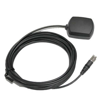
Compact & Sensitive GPS antenna with Excellent Signal Amplification for Mobile Applications
- High performance
- Out-band filtering & rejection
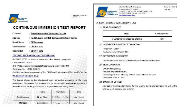
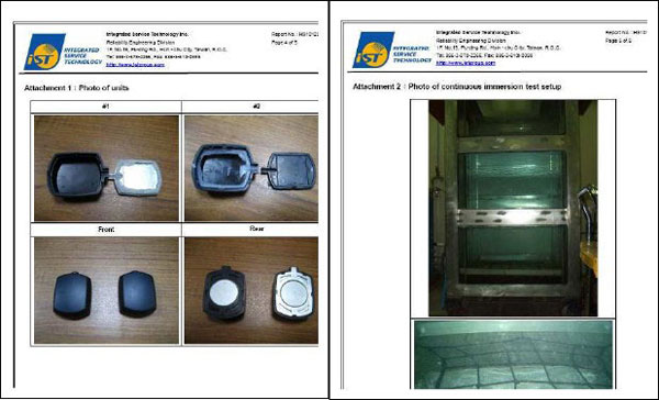
- Fully waterproof
- Voltage: 2.5 V ~5.5 V DC
- Provides excellent signal amplification
GA-25 is the integration of a high performance GPS patch antenna and a state-of-the-art low noise amplifier into a very low profile/ extremely compact/ fully waterproof enclosure which, when connected to a GPS receiver with 2.3~5.5V DC antenna power, provides excellent signal amplification and out-band filtering & rejection, provide 3V or 5V input Voltage is available.
Product Feature
- Compact Construction/ Low Profile/ Fully Waterproof
- Magnet and Screw Mount Base
- Excellent Temperature Stability
- Low Noise Figure
- High Sensitivity
Applications:
- Automobile GPS
- Bluetooth Receiver
- Car Tracking Navigation System
- AVL / Fleet Management Systems
- External Antenna for Handheld GPS
- External Antenna for PDA Navigator
Product Specifications
| Physical Condition | |
|---|---|
| Construction | Polycarbonate- radome at top, die-cast shell at bottom/ rubber gasket for water seal in between |
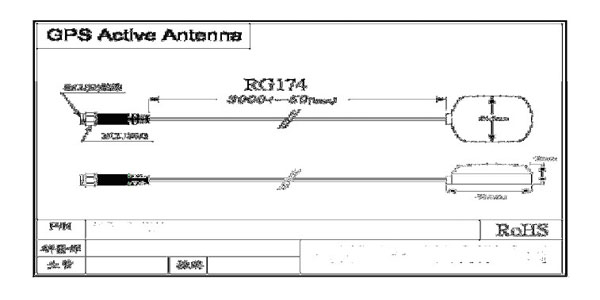
| Dimension | 45.5mm (L) x 34.2mm (W) x 15mm (H) |
| Weight | 80 grams (excluding cable & connector) |
| Standard Mounting | 3M / Magnet mount (Optional) |
| Optional Mounting Plate | customized metal sheet |
| Environmental Conditions | |
| Operation temperature | -40°C to +85°C |
| Storage temperature | -40°C to +100°C |
| Relative Humidity | 95% non-condensing |
| Cable & Connector | |
| Cable | 5 meter RG174/U (standard) cable, other length available |
| Pulling Strength | 6 Kg @ 5sec with molded plastics on connector end for strain relief |
| Connector Available | BNC,TNC,FME (to be adapted), GT5, MCX (OSX), SMA, SMB or SMC in straight or right angle |
| Optional Adapters | Universal Connector Adapter (FME to TNC/BNC/SMA/SMB/MCX) |
| Antenna Element | |
| Center Frequency | 1575.42 MHz +/-1.023MHz |
| Polarization | R.H.C.P. (Right Handed Circular Polarization) |
| Absolute Gain @ Zenith | 3 dBic Typ. |
| Gain | 90 o:2.0dBi min. 20o :-5.0dBi min. Mounted on the 60mm × 60mm square ground plane |
| Axial Ratio | 90o:3 .0dB max. Mounted on the 60mm × 60mm square ground plane |
| Low Noise Amplifier | |
| Center Frequency | 1575.42 MHz +/- 1.023 MHz |
| Gain | 28+/-4.5dB |
| Bandwidth | 10 MHz min. @S11-10 dB |
| Noise Figure | 1.5dB Typ. |
| Filter | 25dB @ fo 50MHz 35dB @ fo 100MHz * fo=1575.42MHz |
| Supply Voltages | 2.5 ~5.5V DC |
| Current Consumption | 2.5V : 6.6mA Typ. 3V: 8.6mA Typ. 4V: 12.6mA Typ. 5V: 16.6mA Typ. |
| Output Impedance | 50 ohm |
| Output VSWR | 2.0 max. |
| Overall Performance(Antenna Element, LNA & Cable) | |
| Frequency range | 1575.42 +/- 1.023 MHz |
| Gain | At 90o 30 ± 4.5dBi-(cable loss) Note:1 Mounted on the 60mm x 60mm square ground plane |
| Output Impedance | 50 ohm |
| VSWR | 2.0 max. |
(This specification is subject to change without prior notice)
Note:1:Cable Loss=(-1.2dB/m)
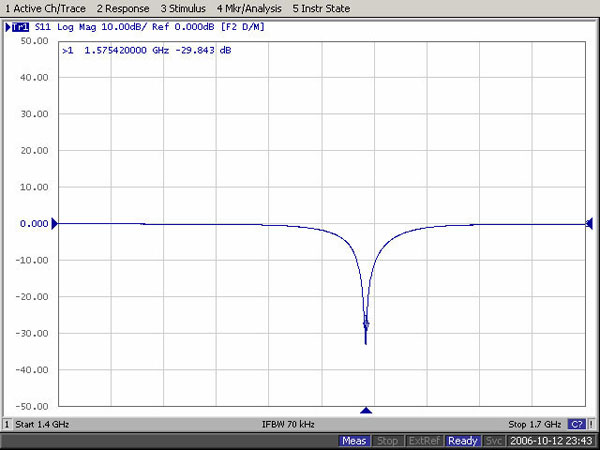
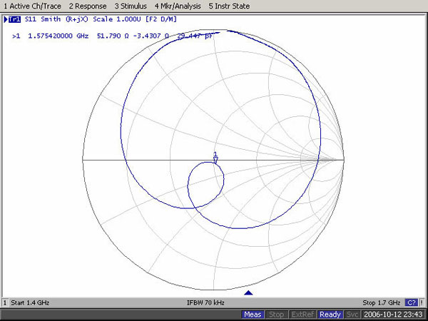
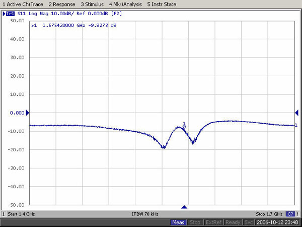
Return loss and Smith Chart for Ceramic Path:
1. Return loss
2. Smith Chart
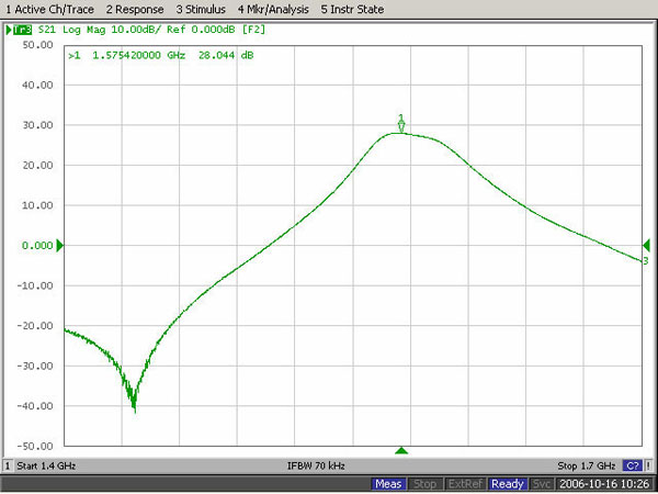
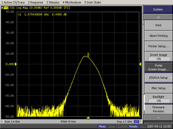
Insertion Gain and I/O Reflection Coefficient for LNA:
1. LNA Insertion Gain
2. LNA Input reflection Coefficient
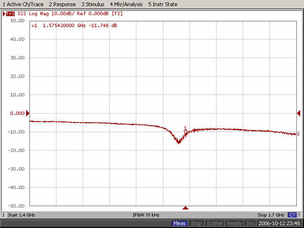
3. LNA Output reflection Coefficient
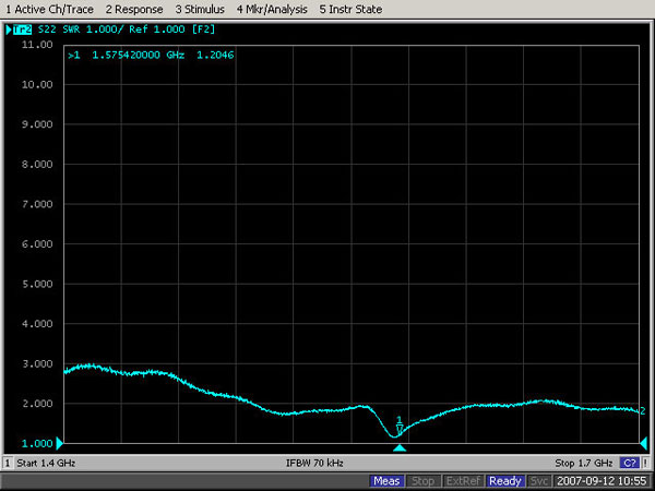
Active Antenna Module:
1. Output VSWR
2. Active antenna Gain
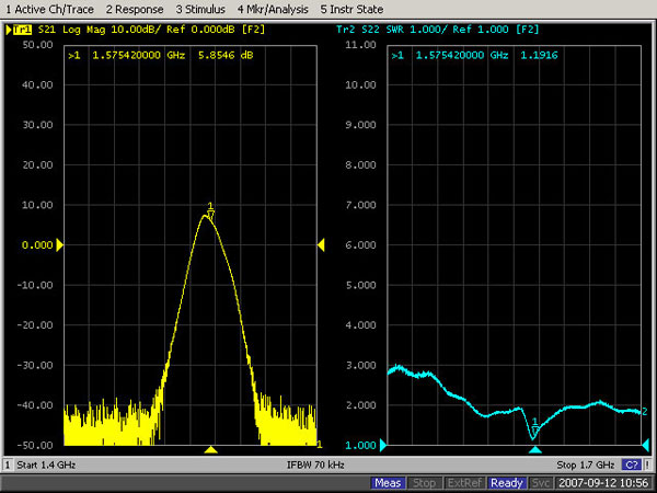
| S-parameter | Highest | Lowest |
| S21(dB) | 11 | 5 |
Note: 50 cm measurement S21> 5dB Pass
| VSWR | ≤ 2 |
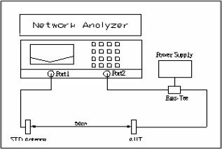 |
*AUT: Antenna on 70x70mm metal pillar |
IEC/EN 60529 IPX8 contunuous:
CE/FCC: