PA-25
 |
|
Product Description
Ceramic Patch Antenna
Model: PA Antenna
This microwave dielectric antenna elements and its series are designed to be used for GPS device. The patch antenna with compact size incorporates a rectangular micro-strip design for GPS C/A right-hand circular polarization wave reception, featuring low RL, low Axial Ratio but high gain, etc.
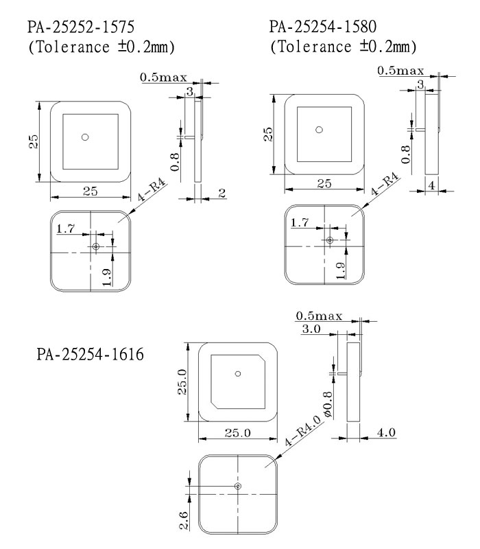
Pin length and outer diameter
Length: 1.6mm (Can depend on the customer demand change, the suggestion length1.9mm & 3.0mm)
Outer diameter: 0.8mm
Structure and Material
| NO. | Description | Structure and Material |
|---|---|---|
| 1 | Antenna Substrate | Dielectric Ceramics |
| 2 | Pin | Copper, Tin Plated |
| 3 | Electrode | Ag Plated |
| 4 | Ground Base | Ag Plated |
| 5 | Adhesive type | 3M |
Environment Performance
| Item | Requirement | Time |
|---|---|---|
| Humidity | +40±2°C,90~95%R.H. | 96 Hours |
| Temperature Life | +80±3°C -40±1°C | 24 Hours |
| Thermal Shock | Cycle:-40°C 30min, +85°C 30min | 5 Cycles |
Mechanical Performance
| Item | Requirement |
|---|---|
| Drop Shock | The device dropped into the hard wooden board from the height of 30cm for 3 times each facet of the 3 dimensions of the device. |
| Vibration | The device applied to the vibration of 10 to 55Hz with amplitude of 1.5mm for 2 hours each in X,Y and Z directions. |
Electric Specification
| Satellite frequency | 1575.42MHz |
|---|---|
| Polarization | Right-hand Circular |
| V.S.W.R. | 1.5 MAX. |
| Return Loss | -15dB MAX. |
| Axial Ratio | 5dB MAX. |
| Impedance | 50Ω |
| Model | Center Frequency (MHz) | Band width (MHz) | VSWR | Gain (dBi) | Dimension (mm) | Ground Plane (mm) |
|---|---|---|---|---|---|---|
| PA25254 | 1585 | ≥10 | ≤1.5 | 4.5 | 25×25×4 | 70×70 |
| 1575 | ≥10 | ≤1.5 | 2.5 | 25×25×4 | 30×30 | |
| PA25252 | 1575 | ≥8 | ≤1.5 | 2.0 | 25×25×2 | 30×30 |
| PA18184 | 1578 | ≥6 | ≤1.5 | 1.5 | 18×18×4 | 20×20 |
| PA18182 | 1580 | ≥5 | ≤1.5 | 1.0 | 18×18×2 | 20×20 |
| PA15154 | 1575 | ≥5 | ≤1.5 | 0.5 | 15×15×4 | 18×18 |
| PA12124 | 1575 | ≥5 | ≤1.5 | -1.0 | 12×12×4 | 15×15 |
| PA10104 | 1582 | ≥5 | ≤1.5 | -2 | 10×10×4 | 12×12 |
Product Specifications
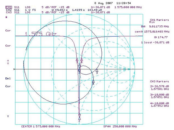
Number: PA-25252-1575
Antenna size: 25*25*2
Tolerance ±0.2mm
Electrical Characteristics:
| Item | Specification | Tolerance |
|---|---|---|
| Range of Receiving Frequency | 1575 | ±2.5 |
| Center Frequency @ 30*30mm Ground Plane | 1575 | ±3.0 |
| Band Width @ Return Loss ≦ -10dB | ≥ 8 | ±0.5 |
| V.S.W.R. @ Center Frequency | ≤1.5 | ±0.5 |
| Peak Gain @ 70*70mm Ground Plane | 4.0 Typical | -- |
| Axial ratio | ≦3 | -- |
| Polarization | Right-Handed Circular | -- |
| Impedance | 50 | -- |
| Frequency Temperature Coefficient | 0±10 | -- |
Return Loss and Smith-chart:
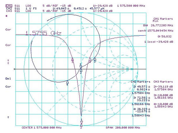
Number: PA-25254-1580
Antenna size: 25*25*4
Tolerance ±0.2mm
Electrical Characteristics:
| Item | Specification | Tolerance |
|---|---|---|
| Range of Receiving Frequency | 1575 | ±2.5 |
| Center Frequency @ 70*70mm Ground Plane | 1580 | ±2.0 |
| Band Width @ Return Loss ≦ -10dB | ≥ 10 | ±0.5 |
| V.S.W.R. @ Center Frequency | ≤1.5 | ±0.5 |
| Peak Gain @ 70*70mm Ground Plane | 4.5 Typical | -- |
| Axial ratio | ≦3 | -- |
| Polarization | Right-Handed Circular | -- |
| Impedance | 50 | -- |
| Frequency Temperature Coefficient | 0±10 | -- |
Return Loss and Smith-chart:
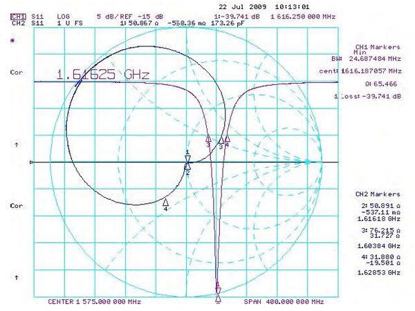
Number: PA-25254-1616
Antenna size: 25*25*4
Electrical Characteristics:
| Item | Specification | Tolerance |
|---|---|---|
| Center Frequency @ 70*70mm Ground Plane | 1616 | ±3.0 |
| Band Width @ Return Loss ≦ -10dB | ≥ 10 | ±0.5 |
| V.S.W.R. @ Center Frequency | ≤1.5 | ±0.5 |
| Peak Gain @ 70*70mm Ground Plane | 4.5 Typical | -- |
| Axial ratio | ≦3 | -- |
| Polarization | Right-Handed Circular | -- |
| Impedance | 50 | -- |
| Frequency Temperature Coefficient | 0±10 | -- |
Return Loss and Smith-chart: